DAF 516
Differenzdruckregler mit stufenlos einstellbarem Sollwert – Montage nur im Vorlauf
Diese kompakten Differenzdruckregler für Heiz- und Kühlanlagen sind überall dort einzusetzen, wo hohe Differenzdruck- oder Temperaturwerte vorliegen. DA 516 sind aber auch zum Einsatz auf der Primär- oder Sekundärseite von Fernheizungsanlagen sowie für Kühlanlagen optimal geeignet. Die Regler sind durch die elektrophoretische Beschichtung des Spärogussgehäuses bestens, gegen Korrosion geschützt.
Produktmerkmale & -vorteile
Inline Design
Ermöglicht hohe Druckverluste bei geringstem Geräusch.
Stufenlos einstellbarer Sollwert
Garantiert eine genaue Differenzdruckregelung.
Technische Beschreibung
Anwendungsbereich:
Heizungs- und Kälteanlagen.
Montage nur im Vorlauf.
Funktionen:
Differenzdruckregelung
Voreinstellung Δp über den Verbraucher (ΔpL)
Dimensionen:
DN 15-125
Druckklasse:
DN 15-50: PN 25
DN 65-125: PN 25 / PN 16
Max. Differenzdruck (ΔpV):
1600 kPa = 16 bar
Einstellbereich:
Δp für den Verbraucher einstellbar im Bereich:
5-30 kPa, 10-60 kPa, 10-100 kPa oder 60-150 kPa.
Liefereinstellung:
DN 15-50: Maximalwert (30, 60, 100 bzw. 150 kPa).
DN 65-125: Mindest-/Höchstwert in der Mitte (~18, ~35, ~55 bzw. ~105 kPa).
Temperatur:
Max. Betriebstemperatur: 150°C
Min. Betriebstemperatur: -10°C
Medien:
Wasser oder neutrale Flüssigkeiten, Wasser-Glykol-Gemische (0 - 57 %).
Werkstoffe:
Ventilgehäuse: Sphäroguss EN-GJS-400-15
Membrane und Dichtungen: EPDM
Einstellring: DN 15-50 Ryton PPS, DN 65-125 R St 37-2 Stahl.
Oberflächenbehandlung:
Elektrophoretische Beschichtung.
Kennzeichnung:
IMI TA, DN, PN, Werkstoff, Kvs, Δp und Durchflussrichtungspfeil.
Anschlüsse:
DN 15-50: Aussengewinde nach ISO 228.
DN 65-125: Flansche nach EN-1092-2, Typ 21. Baulänge nach EN 558 Serie 1.
Artikel
DN 15-50
Außengewinde – Verschiedene Anschlussverschraubungen verfügbar.
Außengewinde gemäß ISO 228.
Im Lieferumfang enthalten: Kapillarrohr (Ø6) 2 x 1.200 mm, Anschlussnippel (G1/2+G3/4) für den Kapillarrohranschluss an z.B. ein STAD und 2 Impulsleitungsanschluss R1/4 (R1/8 am Regler montiert).
PN 25
DN | d | L | L1* | H1 | H2 | Kvs | Kg | EAN | Artikel-Nr. | |
5-30 kPa | ||||||||||
15/20 | G1 | 106 | 116 | 41 | 52 | 4 | 1,5 | 3831112505476 | 52 763-120 | |
25/32 | G1 1/4 | 125 | 150 | 51 | 57 | 12 | 2,6 | 3831112503953 | 52 763-125 | |
40/50 | G2 | 162 | 190 | 70 | 75 | 30 | 5,8 | 3831112504042 | 52 763-140 | |
10-60 kPa | ||||||||||
15/20 | G1 | 106 | 116 | 41 | 52 | 4 | 1,5 | 3831112505377 | 52 761-120 | |
25/32 | G1 1/4 | 125 | 150 | 51 | 57 | 12 | 2,6 | 3831112504134 | 52 761-125 | |
40/50 | G2 | 162 | 190 | 70 | 75 | 30 | 5,8 | 3831112504196 | 52 761-140 | |
10-100 kPa | ||||||||||
15/20 | G1 | 106 | 116 | 41 | 52 | 4 | 1,5 | 3831112504189 | 52 760-120 | |
25/32 | G1 1/4 | 125 | 150 | 51 | 57 | 12 | 2,6 | 3831112504004 | 52 760-125 | |
40/50 | G2 | 162 | 190 | 70 | 75 | 30 | 5,8 | 3831112504103 | 52 760-140 | |
60-150 kPa | ||||||||||
15/20 | G1 | 106 | 116 | 41 | 52 | 4 | 1,5 | 3831112504233 | 52 762-120 | |
25/32 | G1 1/4 | 125 | 150 | 51 | 57 | 12 | 2,6 | 3831112504141 | 52 762-125 | |
40/50 | G2 | 162 | 190 | 70 | 75 | 30 | 5,8 | 3831112504158 | 52 762-140 | |
*) Länge einschl. Einstellring.
Kvs = m3/h bei einem Druckverlust von 1 bar und voll geöffnetem Ventil.
→ = vorgeschriebene Durchflussrichtung.
DN 65-125
Flanschen – Benötigen keine separaten Anschlüsse.
Flansche nach EN 1092-2, Typ 21.
Im Lieferumfang enthalten: Kapillarrohr (Ø6) 2 x 1.500 mm und 2 Impulsleitungsanschluss R1/4 (M14x1 am Regler montiert).
PN 25 (DN 65-80 auch passend für Gegenflansche PN 16)
DN | D | L | Kvs | Kg | EAN | Artikel-Nr. | |
5-30 kPa | |||||||
65 | 210 | 160 | 60 | 18 | 3831112502635 | 52 763-165 | |
80 | 210 | 160 | 60 | 18 | 3831112502819 | 52 763-180 | |
100 | 320 | 254 | 150 | 58 | 3831112502406 | 52 763-190 | |
125 | 320 | 254 | 150 | 58 | 3831112502444 | 52 763-191 | |
10-60 kPa | |||||||
65 | 210 | 160 | 60 | 18 | 3831112504493 | 52 761-165 | |
80 | 210 | 160 | 60 | 18 | 3831112504509 | 52 761-180 | |
100 | 320 | 254 | 150 | 58 | 3831112502390 | 52 761-190 | |
125 | 320 | 254 | 150 | 58 | 3831112502420 | 52 761-191 | |
10-100 kPa | |||||||
65 | 210 | 160 | 60 | 18 | 3831112504677 | 52 760-165 | |
80 | 210 | 160 | 60 | 18 | 3831112504684 | 52 760-180 | |
100 | 320 | 254 | 150 | 58 | 3831112502161 | 52 760-190 | |
125 | 320 | 254 | 150 | 58 | 3831112502413 | 52 760-191 | |
60-150 kPa | |||||||
65 | 210 | 160 | 60 | 18 | 3831112504516 | 52 762-165 | |
80 | 210 | 160 | 60 | 18 | 3831112504615 | 52 762-180 | |
100 | 320 | 254 | 150 | 58 | 3831112505681 | 52 762-190 | |
125 | 320 | 254 | 150 | 58 | 3831112505865 | 52 762-191 | |
PN 16
DN | D | L | Kvs | Kg | EAN | Artikel-Nr. | |
5-30 kPa | |||||||
100 | 320 | 254 | 150 | 58 | 3831112502482 | 52 763-590 | |
125 | 320 | 254 | 150 | 58 | 3831112502536 | 52 763-591 | |
10-60 kPa | |||||||
100 | 320 | 254 | 150 | 58 | 3831112502468 | 52 761-590 | |
125 | 320 | 254 | 150 | 58 | 3831112502512 | 52 761-591 | |
10-100 kPa | |||||||
100 | 320 | 254 | 150 | 58 | 3831112502451 | 52 760-590 | |
125 | 320 | 254 | 150 | 58 | 3831112502505 | 52 760-591 | |
60-150 kPa | |||||||
100 | 320 | 254 | 150 | 58 | 3831112502499 | 52 762-590 | |
125 | 320 | 254 | 150 | 58 | 3831112502543 | 52 762-591 | |
Kvs = m3/h bei einem Druckverlust von 1 bar und voll geöffnetem Ventil.
→ = vorgeschriebene Durchflussrichtung.
Gewinde nach ISO 7. Mit freilaufender Mutter.
Anschluss mit Aussengewinde
Gewinde nach ISO 7.
Mit freilaufender Mutter.
d1 | d2 | L1* | EAN | Artikel-Nr. |
G1 | R1/2 | 34 | 3831112500983 | 52 759-115 |
G1 | R3/4 | 40 | 3831112500990 | 52 759-120 |
G1 1/4 | R1 | 40 | 3831112501003 | 52 759-125 |
G1 1/4 | R1 1/4 | 45 | 3831112501010 | 52 759-132 |
G2 | R1 1/2 | 45 | 3831112503342 | 52 759-140 |
G2 | R2 | 50 | 3831112503472 | 52 759-150 |
*) Baulänge (gemessen von der Dichtung bis zum Anschlussende).
Achtung! Nur auf der Eingangsseite zu verwenden.
Anschluss mit Flansch
Achtung! Nur auf der Eingangsseite zu verwenden.
Flansch nach EN-1092-2:1997, Typ 16.
d1 | d2 | D | L1* | EAN | Artikel-Nr. |
G1 | M12 | 95 | 10 | 3831112501065 | 52 759-515 |
G1 | M12 | 105 | 20 | 3831112501072 | 52 759-520 |
G1 1/4 | M12 | 115 | 5 | 3831112504318 | 52 759-525 |
G1 1/4 | M16 | 140 | 15 | 3831112501096 | 52 759-532 |
G2 | M16 | 150 | 5 | 3831112504325 | 52 759-540 |
G2 | M16 | 165 | 20 | 3831112501317 | 52 759-550 |
*) Baulänge (gemessen von der Dichtung bis zum Anschlussende).
Achtung! Nur auf der Ausgangsseite zu verwenden.
Anschluss mit Flansch (verlängert)
Achtung! Nur auf der Ausgangsseite zu verwenden.
Flansch nach EN-1092-2:1997, Typ 16.
d1 | d2 | D | L1* | EAN | Artikel-Nr. |
G1 | M12 | 95 | 47 | 3831112501157 | 52 759-615 |
G1 | M12 | 105 | 47 | 3831112500136 | 52 759-620 |
G1 1/4 | M12 | 115 | 62 | 3831112503533 | 52 759-625 |
G1 1/4 | M16 | 140 | 62 | 3831112526129 | 52 759-632 |
G2 | M16 | 150 | 72 | 3831112505025 | 52 759-640 |
G2 | M16 | 165 | 72 | 3831112503892 | 52 759-650 |
*) Baulänge (gemessen von der Dichtung bis zum Anschlussende).
Mit freilaufender Mutter
Schweißanschluss
Mit freilaufender Mutter
d1 | D | L1* | EAN | Artikel-Nr. |
G1 | 20,8 | 37 | 3831112500945 | 52 759-315 |
G1 | 26,3 | 42 | 3831112500952 | 52 759-320 |
G1 1/4 | 33,2 | 47 | 3831112500969 | 52 759-325 |
G1 1/4 | 40,9 | 47 | 3831112500976 | 52 759-332 |
G2 | 48,0 | 47 | 3831112501140 | 52 759-340 |
G2 | 60,0 | 52 | 3831112501294 | 52 759-350 |
*) Baulänge (gemessen von der Dichtung bis zum Anschlussende).
Gewinde nach ISO 7-1. Mit freilaufender Mutter.
Anschluss mit Innengewinde Rc
Gewinde nach ISO 7-1.
Mit freilaufender Mutter.
d1 | d2 | L1* | EAN | Artikel-Nr. |
G1 | Rc1/2 | 26 | 3831112527454 | 52 751-301 |
G1 | Rc3/4 | 32 | 3831112527461 | 52 751-302 |
G1 1/4 | Rc1 | 47 | 3831112527478 | 52 751-303 |
G1 1/4 | Rc1 1/4 | 52 | 3831112527485 | 52 751-304 |
G2 | Rc1 1/2 | 52 | 3831112527492 | 52 751-305 |
G2 | Rc2 | 64,5 | 3831112527508 | 52 751-306 |
*) Baulänge (gemessen von der Dichtung bis zum Anschlussende).
Gewinde nach ISO 228.
Anschluss mit Innengewinde
Gewinde nach ISO 228.
Mit freilaufender Mutter.
d1 | d2 | L1* | EAN | Artikel-Nr. |
G1 | G1/2 | 26 | 3831112501027 | 52 759-015 |
G1 | G3/4 | 32 | 3831112501034 | 52 759-020 |
G1 1/4 | G1 | 47 | 3831112501041 | 52 759-025 |
G1 1/4 | G1 1/4 | 52 | 3831112501058 | 52 759-032 |
G2 | G1 1/2 | 52 | 3831112503489 | 52 759-040 |
G2 | G2 | 64,5 | 3831112503205 | 52 759-050 |
*) Baulänge (gemessen von der Dichtung bis zum Anschlussende).
Für Impulsleitung Ø6 mm mit R1/4, R1/8 and M14 Anschluss.
Impulsleitungsanschluss
Für Impulsleitung Ø6 mm mit R1/4, R1/8 and M14 Anschluss.
DN 15-50: 2 Stk. R1/4 sind im Lieferumfang des Reglers DAF 516 enthalten (2 Stk. R1/8 am Regler montiert).
DN 65-125: 2 Stk. R1/4 sind im Lieferumfang des Reglers DAF 516 enthalten (2 Stk. M14x1 am Regler montiert).
DN | EAN | Artikel-Nr. | |
6 x R1/4 | 15-125 | 3831112527355 | 52 759-201 |
6 x R1/8 | 15-32 | 3831112533868 | 52 759-213 |
6 x R1/8 | 40-50 | 3831112533875 | 52 759-218 |
6 x M14x1 | 65-125 | 3831112535145 | 52 759-214 |
Messing/EPDM
Entlüftungsschraube
Messing/EPDM

d | EAN | Artikel-Nr. |
M6 | 3831112527980 | 52 759-211 |
Zum Einsatz bei Wärmedämmungen.Rostfreier Stahl/EPDM/Messing.
Entlüftungsverlängerung
Zum Einsatz bei Wärmedämmungen.
Rostfreier Stahl/EPDM/Messing.
d | D | L | EAN | Artikel-Nr. |
M6 | 12 | 70 | 3831112531727 | 52 759-220 |
Zu Verwendung mit STAD beim Anschluss eines Kapillarrohrs von 6 mm.
Anschluss-Satz STAD
Zu Verwendung mit STAD beim Anschluss eines Kapillarrohrs von 6 mm.
2 Anschlussnippel (G1/2 + G3/4), 1 Druckmutter (Ø6mm), 1 Kone und 1 Stützhülse sind im Lieferumfang des DAF 516, DN 15-50, enthalten.
d | EAN | Artikel-Nr. |
G1/2 | 7318793850003 | 52 762-006 |
G3/4 | 7318793850102 | 52 762-106 |
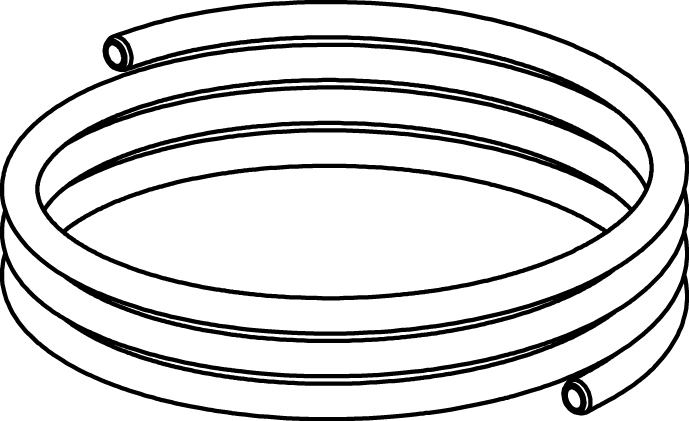
Impulsleitung
Ø6 mm
2 Stücke sind im Lieferumfang des Reglers DAF 516 enthalten.
L [m] | Ø | DN | EAN | Artikel-Nr. |
1,2 | 6 mm | 15-50 | 3831112527157 | 52 759-215 |
1,5 | 6 mm | 65-125 | 3831112527164 | 52 759-265 |
Anschluss Impulsleitung mit Absperrung
Für Impulsleitungsanschluss Ø6 mm an STAF/STAF-SG.
d | D | Für DN | EAN | Artikel-Nr. |
G1/4 | 6 | 20-50 | 7318793999504 | 52 265-209 |
G3/8 | 6 | 65-400 | 7318793999405 | 52 265-208 |
Bilder

52762125
Format auswählen Download
52763140
Format auswählen Download
52760140
Format auswählen Download
DAF516_DN25_DN80_CAD
Format auswählen Download
52761180
Format auswählen Download
52763125
Format auswählen Download
52761125
Format auswählen Download
52761190
Format auswählen Download
52763591
Format auswählen Download
52762140
Format auswählen Download
52763165
Format auswählen Download
52762190
Format auswählen Download
52760591
Format auswählen Download
52763180
Format auswählen Download
52761120
Format auswählen Download
52761591
Format auswählen Download
52762590
Format auswählen Download
52763190
Format auswählen Download
52761590
Format auswählen Download
52762591
Format auswählen Download
52762180
Format auswählen Download
DAF516_DN25_32_CAD
Format auswählen Download
52761165
Format auswählen Download
52762191
Format auswählen Download
52763120
Format auswählen Download
52760590
Format auswählen Download
52763191
Format auswählen Download
52763590
Format auswählen Download
52760191
Format auswählen Download
52760120
Format auswählen Download
52760190
Format auswählen Download
52762120
Format auswählen Download
52762165
Format auswählen Download
DAF516_DN80_CAD
Format auswählen Download
52760125
Format auswählen Download
52760165
Format auswählen Download
52761191
Format auswählen Download
52761140
Format auswählen Download