DA 516
Differential pressure controller with adjustable set-point – DN 15-50
This compact differential pressure controller for heating and cooling systems is particularly effective in situations requiring high temperatures and/or pressure drop. DA 516 can be used both on the primary and secondary side in district heating and comfort cooling systems. Rust protection is assured thanks to the electrophoretic painted ductile iron body.
Features & Benefits
Inline design
Inline flow allows high pressure drops without noise.
Adjustable set-point
Delivers desired differential pressure ensuring accurate balancing.
Measuring point
Simplifies the balancing procedure, increases its accuracy and enables troubleshooting.
Technical Information
Application:
Heating and cooling systems.
Installation in the return pipe.
Functions:
Differential pressure control
Pre-setting Δp over the load (ΔpL)
Measuring (ΔpL)
Dimensions:
DN 15-50
Pressure class:
PN 25
Max. differential pressure (ΔpV):
1600 kPa = 16 bar
Setting range:
Δp over the load is adjustable within:
5-30 kPa, 10-60 kPa, 10-100 kPa or 60-150 kPa.
Delivery setting:
Maximum value (30, 60, 100 resp. 150 kPa).
Temperature:
Max. working temperature:
- with measuring points: 120°C
- without measuring points: 150°C
Min. working temperature: -10°C
Media:
Water or neutral fluids, water-glycol mixtures (0-57%).
Material:
Valve body: Ductile iron EN-GJS-400-15
Diaphragms and gaskets: EPDM
Adjustment ring: Ryton PPS
Surface treatment:
Electrophoretic painting.
Marking:
IMI TA, DN, PN, Material, Kvs, Δp and flow direction arrow.
Connection:
Male thread according to ISO 228.
Articles
Without measuring points (max. 150°C)
Male thread – Separate connections optional.
Male threads according to ISO 228.
Included: Capillary pipe (Ø6) 1 200 mm, connection set (G1/2+G3/4) for capillary pipe to e.g. STAD and 1 capillary pipe connection R1/4 (R1/8 mounted on valve).
PN 25
DN | d | L | L1* | H1 | H2 | Kvs | Kg | EAN | Article No | |
5-30 kPa | ||||||||||
15/20 | G1 | 106 | 116 | 41 | 57 | 4 | 1,5 | 3831112528468 | 52 752-720 | |
25/32 | G1 1/4 | 125 | 150 | 51 | 70 | 12 | 2,6 | 3831112528659 | 52 752-725 | |
40/50 | G2 | 162 | 190 | 70 | 82 | 30 | 5,8 | 3831112528697 | 52 752-740 | |
10-60 kPa | ||||||||||
15/20 | G1 | 106 | 116 | 41 | 57 | 4 | 1,5 | 3831112528451 | 52 754-620 | |
25/32 | G1 1/4 | 125 | 150 | 51 | 70 | 12 | 2,6 | 3831112528642 | 52 754-625 | |
40/50 | G2 | 162 | 190 | 70 | 82 | 30 | 5,8 | 3831112528680 | 52 754-640 | |
10-100 kPa | ||||||||||
15/20 | G1 | 106 | 116 | 41 | 57 | 4 | 1,5 | 3831112528444 | 52 760-320 | |
25/32 | G1 1/4 | 125 | 150 | 51 | 70 | 12 | 2,6 | 3831112528635 | 52 760-325 | |
40/50 | G2 | 162 | 190 | 70 | 82 | 30 | 5,8 | 3831112528673 | 52 760-340 | |
60-150 kPa | ||||||||||
15/20 | G1 | 106 | 116 | 41 | 57 | 4 | 1,5 | 3831112528475 | 52 760-920 | |
25/32 | G1 1/4 | 125 | 150 | 51 | 70 | 12 | 2,6 | 3831112528666 | 52 760-925 | |
40/50 | G2 | 162 | 190 | 70 | 82 | 30 | 5,8 | 3831112528703 | 52 760-940 | |
*) Length incl adjustment ring.
Kvs = m3/h at a pressure drop of 1 bar and fully open valve.
→ = Flow direction
With measuring points (max. 120°C)
Male thread – Separate connections optional.
Male threads according to ISO 228.
Included: Capillary pipe (Ø6) 1 200 mm, connection set (G1/2+G3/4) for capillary pipe to e.g. STAD and 1 capillary pipe connection R1/4 (R1/8 mounted on valve).
PN 25
DN | d | L | L1* | H1 | H2 | Kvs | Kg | EAN | Article No | |
5-30 kPa | ||||||||||
15/20 | G1 | 106 | 116 | 41 | 85 | 4 | 1,5 | 3831112507111 | 52 795-020 | |
25/32 | G1 1/4 | 125 | 150 | 51 | 98 | 12 | 2,6 | 3831112507159 | 52 795-025 | |
40/50 | G2 | 162 | 190 | 70 | 110 | 30 | 5,8 | 3831112507197 | 52 795-040 | |
10-60 kPa | ||||||||||
15/20 | G1 | 106 | 116 | 41 | 85 | 4 | 1,5 | 3831112507104 | 52 795-120 | |
25/32 | G1 1/4 | 125 | 150 | 51 | 98 | 12 | 2,6 | 3831112507142 | 52 795-125 | |
40/50 | G2 | 162 | 190 | 70 | 110 | 30 | 5,8 | 3831112507180 | 52 795-140 | |
10-100 kPa | ||||||||||
15/20 | G1 | 106 | 116 | 41 | 85 | 4 | 1,5 | 3831112507098 | 52 795-220 | |
25/32 | G1 1/4 | 125 | 150 | 51 | 98 | 12 | 2,6 | 3831112507135 | 52 795-225 | |
40/50 | G2 | 162 | 190 | 70 | 110 | 30 | 5,8 | 3831112507173 | 52 795-240 | |
60-150 kPa | ||||||||||
15/20 | G1 | 106 | 116 | 41 | 85 | 4 | 1,5 | 3831112507128 | 52 795-320 | |
25/32 | G1 1/4 | 125 | 150 | 51 | 98 | 12 | 2,6 | 3831112507166 | 52 795-325 | |
40/50 | G2 | 162 | 190 | 70 | 110 | 30 | 5,8 | 3831112507203 | 52 795-340 | |
*) Length incl adjustment ring.
Kvs = m3/h at a pressure drop of 1 bar and fully open valve.
→ = Flow direction
Threads according to ISO 228.
With female thread
Threads according to ISO 228.
Swivelling nut
d1 | d2 | L1* | EAN | Article No |
G1 | G1/2 | 26 | 3831112501027 | 52 759-015 |
G1 | G3/4 | 32 | 3831112501034 | 52 759-020 |
G1 1/4 | G1 | 47 | 3831112501041 | 52 759-025 |
G1 1/4 | G1 1/4 | 52 | 3831112501058 | 52 759-032 |
G2 | G1 1/2 | 52 | 3831112503489 | 52 759-040 |
G2 | G2 | 64,5 | 3831112503205 | 52 759-050 |
*) Fitting length (from the gasket surface to the end of the connection).
Threads according to ISO 7Swivelling nut
With male thread
Threads according to ISO 7
Swivelling nut
d1 | d2 | L1* | EAN | Article No |
G1 | R1/2 | 34 | 3831112500983 | 52 759-115 |
G1 | R3/4 | 40 | 3831112500990 | 52 759-120 |
G1 1/4 | R1 | 40 | 3831112501003 | 52 759-125 |
G1 1/4 | R1 1/4 | 45 | 3831112501010 | 52 759-132 |
G2 | R1 1/2 | 45 | 3831112503342 | 52 759-140 |
G2 | R2 | 50 | 3831112503472 | 52 759-150 |
*) Fitting length (from the gasket surface to the end of the connection).
Swivelling nut
For welding
Swivelling nut
d1 | D | L1* | EAN | Article No |
G1 | 20,8 | 37 | 3831112500945 | 52 759-315 |
G1 | 26,3 | 42 | 3831112500952 | 52 759-320 |
G1 1/4 | 33,2 | 47 | 3831112500969 | 52 759-325 |
G1 1/4 | 40,9 | 47 | 3831112500976 | 52 759-332 |
G2 | 48,0 | 47 | 3831112501140 | 52 759-340 |
G2 | 60,0 | 52 | 3831112501294 | 52 759-350 |
*) Fitting length (from the gasket surface to the end of the connection).
Threads according to ISO 7-1Swivelling nut
With female thread Rc
Threads according to ISO 7-1
Swivelling nut
d1 | d2 | L1* | EAN | Article No |
G1 | Rc1/2 | 26 | 3831112527454 | 52 751-301 |
G1 | Rc3/4 | 32 | 3831112527461 | 52 751-302 |
G1 1/4 | Rc1 | 47 | 3831112527478 | 52 751-303 |
G1 1/4 | Rc1 1/4 | 52 | 3831112527485 | 52 751-304 |
G2 | Rc1 1/2 | 52 | 3831112527492 | 52 751-305 |
G2 | Rc2 | 64,5 | 3831112527508 | 52 751-306 |
*) Fitting length (from the gasket surface to the end of the connection).
Attention! Can be used on the inlet side only.
With flange
Attention! Can be used on the inlet side only.
Flange according to EN-1092-2:1997, type 16.
d1 | d2 | D | L1* | EAN | Article No |
G1 | M12 | 95 | 10 | 3831112501065 | 52 759-515 |
G1 | M12 | 105 | 20 | 3831112501072 | 52 759-520 |
G1 1/4 | M12 | 115 | 5 | 3831112504318 | 52 759-525 |
G1 1/4 | M16 | 140 | 15 | 3831112501096 | 52 759-532 |
G2 | M16 | 150 | 5 | 3831112504325 | 52 759-540 |
G2 | M16 | 165 | 20 | 3831112501317 | 52 759-550 |
*) Fitting length (from the gasket surface to the end of the connection).
Attention! Must be used on the outlet side.
With flange (extended)
Attention! Must be used on the outlet side.
Flange according to EN-1092-2:1997, type 16.
d1 | d2 | D | L1* | EAN | Article No |
G1 | M12 | 95 | 47 | 3831112501157 | 52 759-615 |
G1 | M12 | 105 | 47 | 3831112500136 | 52 759-620 |
G1 1/4 | M12 | 115 | 62 | 3831112503533 | 52 759-625 |
G1 1/4 | M16 | 140 | 62 | 3831112526129 | 52 759-632 |
G2 | M16 | 150 | 72 | 3831112505025 | 52 759-640 |
G2 | M16 | 165 | 72 | 3831112503892 | 52 759-650 |
*) Fitting length (from the gasket surface to the end of the connection).
Must be used on STAD when connection of Ø6 mm capillary pipe.
Connection set STAD
Must be used on STAD when connection of Ø6 mm capillary pipe.
2 transition nipples (G1/2 and G3/4), 1 thrust nut (Ø6), 1 cone and 1 support bush are included in DA 516.
d | EAN | Article No |
G1/2 | 7318793850003 | 52 762-006 |
G3/4 | 7318793850102 | 52 762-106 |
Capillary pipe connection with shut-off
For connection of Ø6 mm capillary pipe to STAF/STAF-SG.
d | D | For DN | EAN | Article No |
G1/4 | 6 | 20-50 | 7318793999504 | 52 265-209 |
G3/8 | 6 | 65-400 | 7318793999405 | 52 265-208 |
Max 120°C (intermittent 150°C)AMETAL®/EPDM
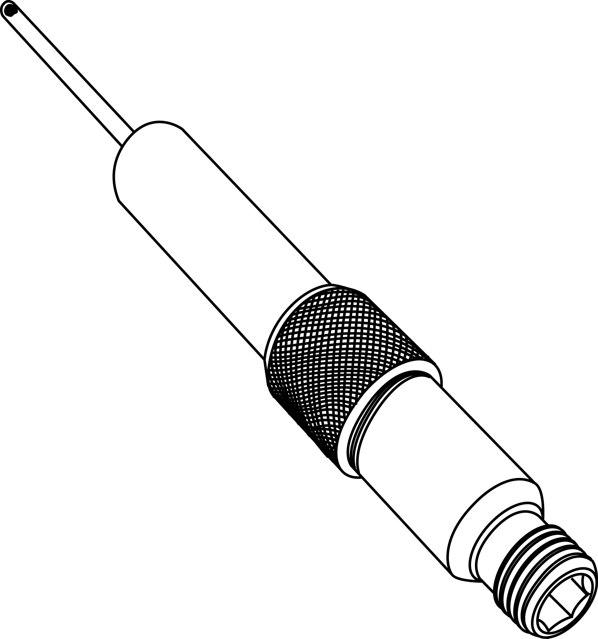
Measuring point
Max 120°C (intermittent 150°C)
AMETAL®/EPDM

d | L | EAN | Article No |
M14x1 | 44 | 7318792813207 | 52 179-014 |
M14x1 | 103 | 7318793858108 | 52 179-015 |
For connection of Ø6 mm copper pipe while permitting simultaneous use of our balancing instrument.
Measuring point, two-way
For connection of Ø6 mm copper pipe while permitting simultaneous use of our balancing instrument.
D | H | EAN | Article No |
6 | 68 | 7318793848703 | 52 179-206 |
Can be installed without draining of the system.AMETAL®/Stainless steel/EPDM
Measuring point, extension 60 mm
Can be installed without draining of the system.
AMETAL®/Stainless steel/EPDM
L | EAN | Article No |
60 | 7318792812804 | 52 179-006 |
Brass/EPDM
Venting screw
Brass/EPDM

d | EAN | Article No |
M6 | 3831112527980 | 52 759-211 |
Capillary pipe
Ø6 mm
1 pc included in DA 516.
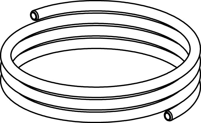
L [m] | Ø | EAN | Article No |
1,2 | 6 mm | 3831112527157 | 52 759-215 |
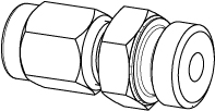
For capillary pipe Ø6 mm with R1/4 and R1/8 connection.
Capillary pipe connection
For capillary pipe Ø6 mm with R1/4 and R1/8 connection.
1 pc R1/4 included in DA 516 (R1/8 mounted on valve)
DN | EAN | Article No | |
6 x R1/4 | 15-50 | 3831112527355 | 52 759-201 |
6 x R1/8 | 15-32 | 3831112533868 | 52 759-213 |
6 x R1/8 | 40-50 | 3831112533875 | 52 759-218 |
Suitable when insulation is used.Stainless steel/EPDM/Brass.
Venting extension
Suitable when insulation is used.
Stainless steel/EPDM/Brass.
d | D | L | EAN | Article No |
M6 | 12 | 70 | 3831112531727 | 52 759-220 |
Photos

52760325
Select a format Download
52760320
Select a format Download
52762106
Select a format Download
52752720
Select a format Download
52754625
Select a format Download
52762006
Select a format Download
52754620
Select a format Download
52795120
Select a format Download
52795140
Select a format Download
52795340
Select a format Download
52795225
Select a format Download
52760940
Select a format Download
52754640
Select a format Download
52752740
Select a format Download
52795240
Select a format Download
52795220
Select a format Download
52760925
Select a format Download
52760920
Select a format Download
52795025
Select a format Download
52795125
Select a format Download
52795020
Select a format Download
52752725
Select a format Download
52795040
Select a format Download
DA516_DN15_20_pers_kat
Select a format Download
DA516_DN15_20_w-o_m-point_persp
Select a format Download
52760340
Select a format Download
52795320
Select a format Download